POPPUR爱换
标题: 和硕IPXSB-DM/H61/itx主板DC-19V/HP p2-1400l/1155一体机工控机 GZ包邮200元 [打印本页]
作者: jusage 时间: 2015-2-9 12:50
标题: 和硕IPXSB-DM/H61/itx主板DC-19V/HP p2-1400l/1155一体机工控机 GZ包邮200元
和硕IPXSB-DM/H61/itx主板DC-19V/HP p2-1400l/1155一体机工控机http://item.taobao.com/item.htm?spm=a1z10.3-c.w4002-2295003698.63.Iy6Jl4&id=25432604386
[size=14.44444465637207px]北京中关村E世界B3164 13810033194
[size=14.44444465637207px]本店也有低功耗G530T(190元)以及G640T(320元)配本款主板可以一起选购。
[size=14.44444465637207px]本款itx主板H61目前主流的 CPU都支持, G1610啦,G2030等,i3,i5都支持。
| |
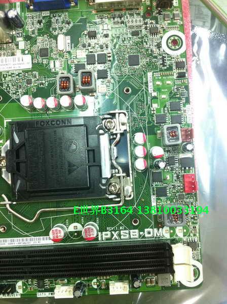
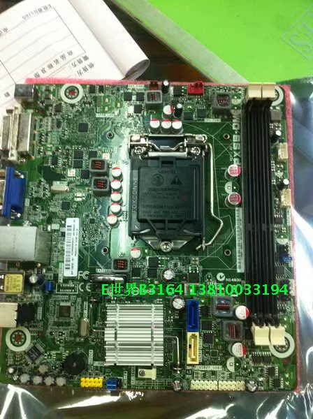
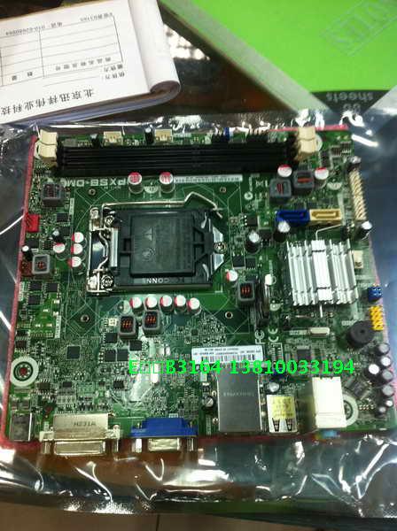
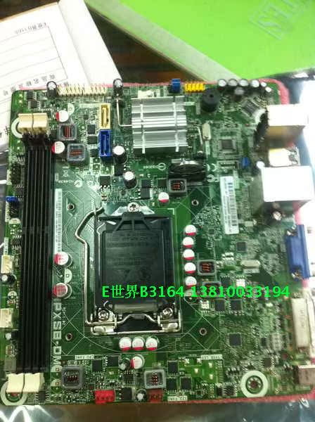
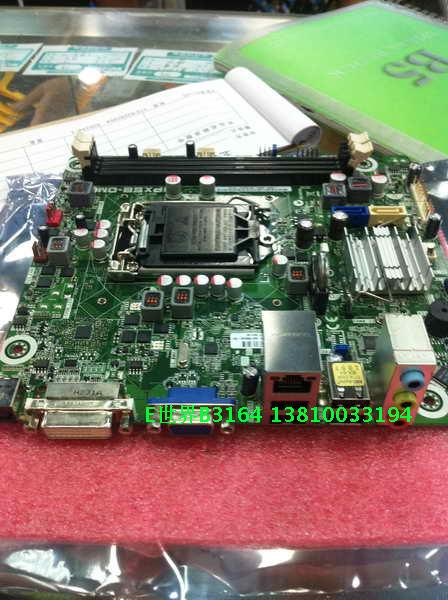
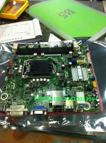
| HP惠普MINI主板H61,IPXSB-DM | 和硕(华硕的子公司)给HP惠普代工的H61,型号IPXSB-DM,MINI-ITX主板,是HP HP p2-1400l Desktop PC系列型号的主机板,17*19 CM,采用H61芯片,支持35W的1155接口SNB,LVY的处理器,两条DDR3内存插槽,最大支持16G内存,带有2个SATA接口,DVI+VGA接口,是组建家庭影院,HTPC最佳选择,DC-19V供电。
主板是工厂库存货,成色近全新,有配挡板,和数据线和给硬盘供电的电源线,质保三个月。
|
|
[size=14.44444465637207px]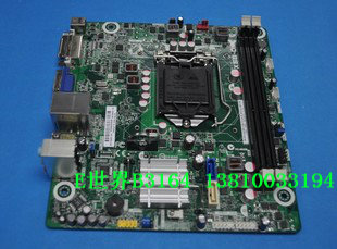
[size=14.44444465637207px]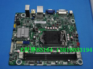
[size=14.44444465637207px]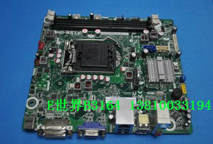
[size=14.44444465637207px]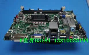
[size=14.44444465637207px]主板支持以下处理器升级:
[size=14.44444465637207px]处理器
[size=14.44444465637207px]英特尔酷睿 i3-32xxT (Ivy Bridge) 双核
[size=14.44444465637207px]英特尔酷睿 i5-34xxT (Ivy Bridge) 双核
[size=14.44444465637207px]Intel 奔腾 G21xxT (Ivy Bridge)
[size=14.44444465637207px]英特尔酷睿 i3-21xx (Sandy Bridge) 双核
[size=14.44444465637207px]英特尔酷睿 i3-21xxT (Sandy Bridge) 双核
[size=14.44444465637207px]英特尔酷睿 i5-23xx (Sandy Bridge) 双核
[size=14.44444465637207px]英特尔奔腾 G4xx (Sandy Bridge) 单核
[size=14.44444465637207px]英特尔奔腾 G5xxT(Sandy Bridge) 双核
[size=14.44444465637207px]英特尔奔腾 G6xx (Sandy Bridge) 单核
[size=14.44444465637207px]英特尔奔腾 G6xxT (Sandy Bridge) 双核
Photograph of motherboard
[size=1.4em]Motherboard description
- Manufacturer's motherboard name: Pegatron
- Motherboard name: IPXSB-DM
- HP/Compaq name: Cork
[size=1.4em]Form Factor
- Mini-ITX : 17 cm (6.7 inches) x 19 cm (7.5 inches)
[size=1.4em]Chipset
[size=1.4em]Front-side bus speed
[size=1.4em]Processor upgrade information
- Socket type: LGA 1155
- Motherboard supports the following processor upgrades:
- Celeron G440 (Sandy Bridge)
- Celeron G530T (Sandy Bridge)
- Core i3-2100T (Sandy Bridge) dual core
- Pentium G6xxT (Sandy Bridge) dual core
[size=1.4em]Memory upgrade information
- Dual channel memory architecture
- Two 240-pin DDR3 UDIMM sockets
- Supports DDR3 UDIMMs
- PC3 8500 (1066 MHz)
- PC3 10600 (1333 MHz)
- Non-ECC memory only, unbuffered
- Supports up to 4 GB on 32-bit* systems
- Supports up to 16 GB on 64-bit systems (with 8 GB UDIMMs)
| NOTE: | 32-bit systems cannot address a full 4.0 GB of memory |
[size=1.4em]Video
[size=1.4em]Intel PCH Integrated graphics
*Integrated video is not available if a graphics card is installed.
- VGA port
- DVI port
- VGA and DVI ports can be used at the same time
[size=1.4em]Audio
[size=1.4em]Integrated Realtek ALC662 Audio
*Integrated audio is not available if a sound card is installed
- 6 channel audio
- Realtek ALC662 CODEC
[size=1.4em]Network
[size=1.4em]LAN: 10-Base-T
- Technology: Atheros AR8152 ethernet controller
- Data transfer speeds: up to 10/100 Mb/s
- Transmission standards: 10-Base-T Ethernet
[size=1.4em]I/O Ports
[size=1.4em]Back I/O ports
Figure 2: Back I/O panel
[size=0.9em]1 - DC power
[size=0.9em]2 - DVI-D port
[size=0.9em]3 - VGA port
[size=0.9em]4 - LAN
[size=0.9em]5 - USB 2.0: 4
[size=0.9em]6 - Audio: Line in
[size=0.9em]7 - Audio: Line out
[size=0.9em]8 - Audio: Microphone
[size=1.4em]Internal Connectors
- 1x CPU fan connector
- 1x System fan connector
- 2x SATA connectors
- 2x SATA power connectors
- 2x USB 2.0 connectors
- 1x Front panel audio connector
- 1x ROM recovery connector
- 1x Front panel connector
[size=1.4em]Clearing the CMOS settings
| CAUTION: | Do not change any jumper setting while the computer is on. Damage to the motherboard can result. |
This motherboard has a jumper to clear the Real Time Clock (RTC) RAM in CMOS.
- Turn OFF the computer and unplug the power cord.
- Move the jumper to from pins 6-4 (default) to pins 4-2 for 5 to 10 secs, then move the jumper back to default.
- Plug the power cord and turn ON the computer.
- During the start-up process, enter BIOS setup to re-enter user settings
[size=1.4em]Clearing the PASSWORD settings
The BIOS password is used to protect BIOS settings from unwanted changes.
To erase the BIOS password follow these steps:
- Turn OFF the computer.
- Move the jumper to Clear from pins 5-3 (default) to pins 3-1.
- Turn ON the computer to POST screen.
- Turn OFF the computer.
- Move the jumper back to default.
- Enter BIOS setup to verify or configure new settings.
[size=1.4em]Motherboard Layout
Figure 3: Motherboard Layout
Motherboard Layout Image
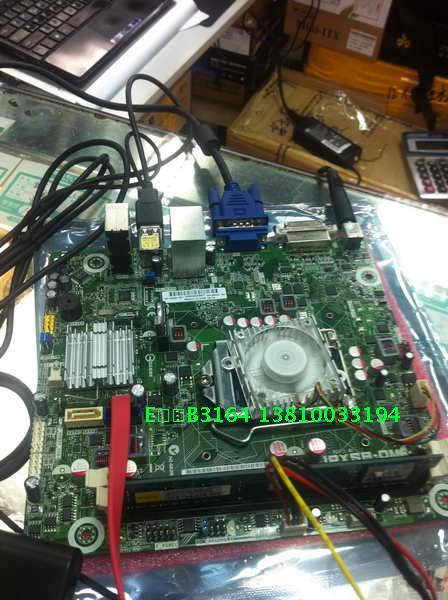
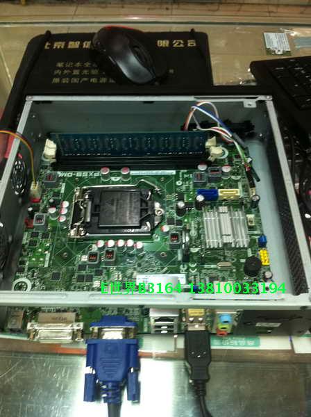
实物图:
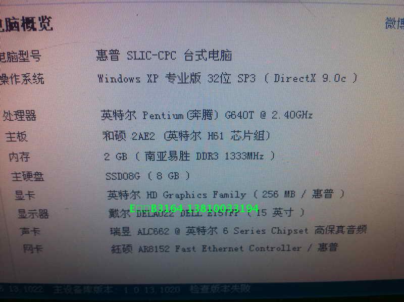
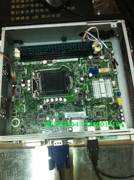
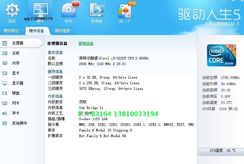
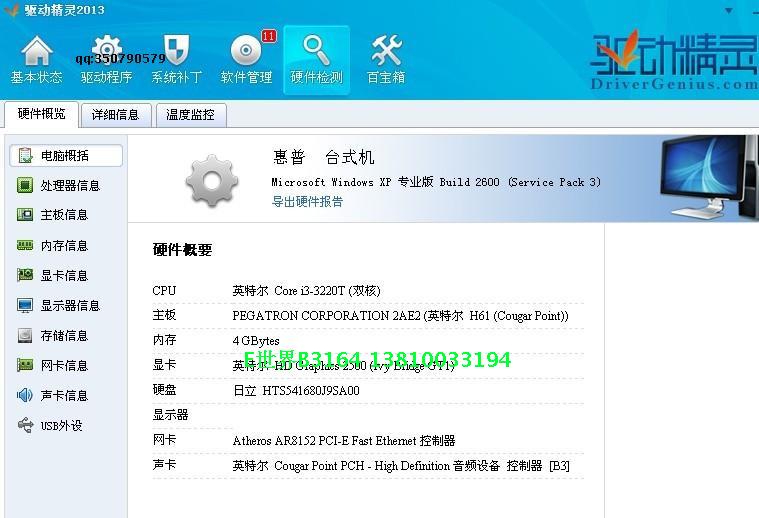
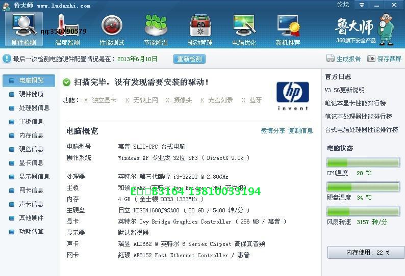
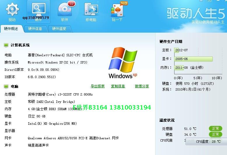
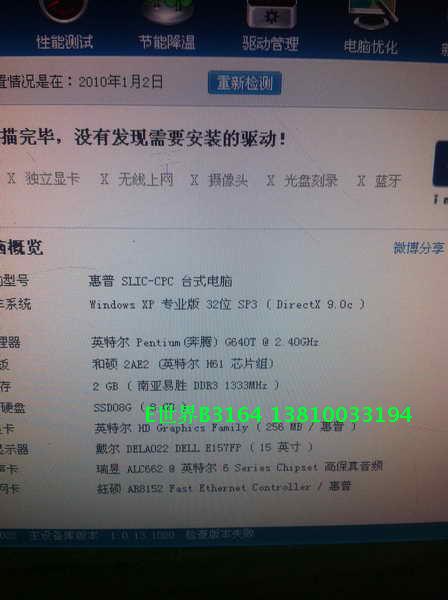
主板测试截图:
~~~~~~~~~~~~~~~~~~~~~~~~~~~~~~~~~~~~~~~~~~~~~~~~~~~~~~~~
| 欢迎光临 POPPUR爱换 (https://we.poppur.com/) |
Powered by Discuz! X3.4 |


