This page details the modifications I'm making to a set of E-Mu 0404 soundcards. There's been a fair amount of talk on some of the forums about improving what appears to be already a good card. Most of the talk on head-fi and diyaudio is about replacing the output op-amp, bridging a different set of op-amps, and replacing some capacitors. Also biasing the last op-amp into class-A operation. What I haven't read is discussion of eliminating the DB-9 dongle with the 1/4" TRS connector for analog out. That can't be that great. My goal is to entirely remove the DB9 and DB15 connectors and replace the back chassis slot with one that holds two high-quality RCA connectors; maybe three so that S/PDIF output is still available. Inputs are not a consideration in this modification. I'm also pondering if bridging the buffer op-amps is the best way to go -- they should help buffer the DAC. Maybe the best thing is to replace the two buffer opamps and bridge the output op-amp so that better channel separation can be maintained? Not sure; I'll have to start by taking a closer look at the board. The replacement opamp will be the Linear Technologies LT1364, an almost direct replacement for the existing JRC NJM2068. But better specs all the way around. Regarding capacitors, it looks as if several can be replaced, with a few more added for good measure and additional bypassing. On order are:
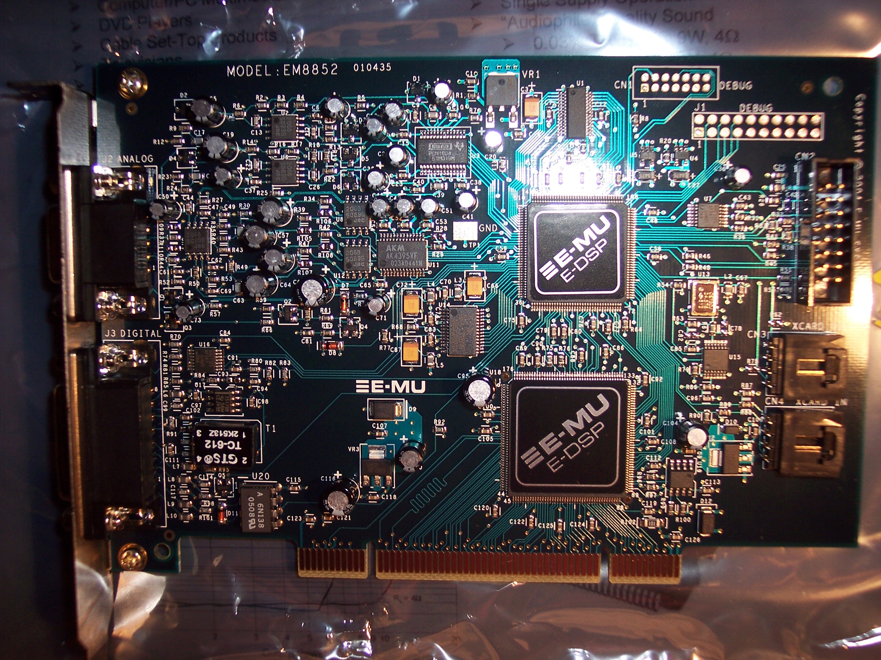
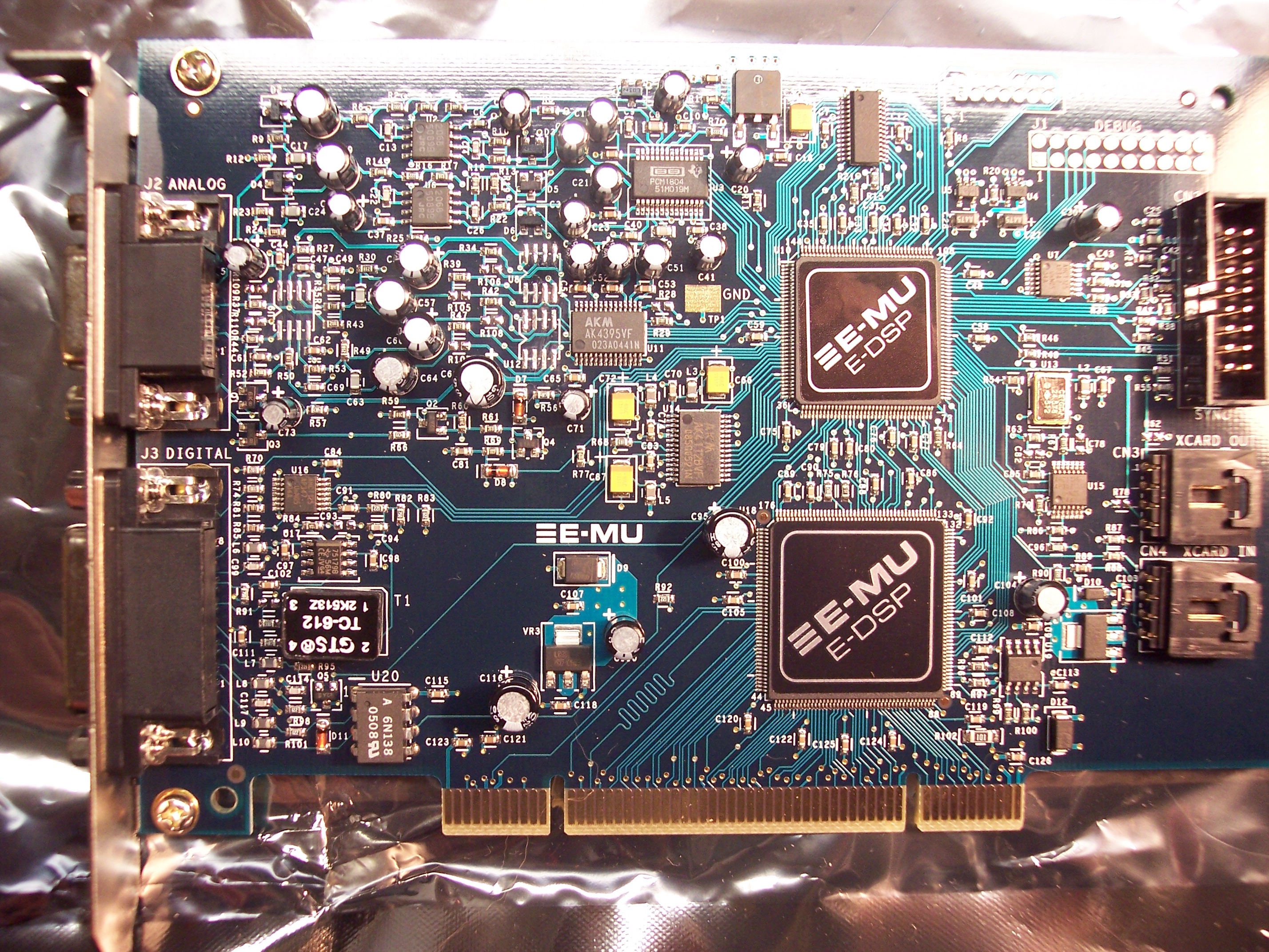 I have the circuit traced from the AKM DAC to the output pins. The first set of JRC opamps are strictly unity gain followers for the + and - outputs of the DAC. The balanced output from the buffer amps goes goes through a 1.3K resistor and into the capacitors, now removed, slated to be replaced. From there the signal heads to the final opamp, configured in what at first glance appears to be a Sallen-Key low-pass filter. At what frequency, I don't yet know. However, the datasheet for the AKM DAC does suggest that this should be done. I'll have to model the circuit to see what's really going on, and if any additional components should be replaced. I have the circuit traced from the AKM DAC to the output pins. The first set of JRC opamps are strictly unity gain followers for the + and - outputs of the DAC. The balanced output from the buffer amps goes goes through a 1.3K resistor and into the capacitors, now removed, slated to be replaced. From there the signal heads to the final opamp, configured in what at first glance appears to be a Sallen-Key low-pass filter. At what frequency, I don't yet know. However, the datasheet for the AKM DAC does suggest that this should be done. I'll have to model the circuit to see what's really going on, and if any additional components should be replaced. 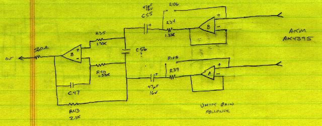 Kinda interesting, R105-R108 are missing on the board. If these were populated, it would provide a bridge directly from the input of the buffer op-amp to the input of the larger caps that are to be replaced. Also have the pinout for the dongles... Kinda interesting, R105-R108 are missing on the board. If these were populated, it would provide a bridge directly from the input of the buffer op-amp to the input of the larger caps that are to be replaced. Also have the pinout for the dongles...
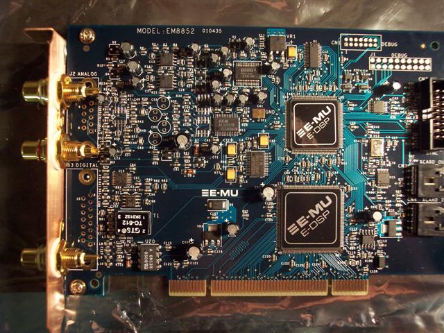 The back bracket has been finished with RCA jacks and mated to the card. The PCI bracket is custom made from copper sheet stock. The DB-15 and DB-9 connectors for the digital and analog connections have been removed -- now I can go straight from the card to the RCA jack. I'll likely include a pin on the unmodified inputs so that the output can be jumpered to the input for RMAA measurements. All the parts have arrived -- I can probably get to re-stuffing the card sometime this weekend. Tue May 31/Wed June 1 Power problems in the workshop. I've spent the last two days on an unplanned re-do of the AC power to the shop and now have three dedicated runs of 10/2 feeding different areas in the shop along with a separate breaker panel just for shop power. What a pain. I'm glad that's done. The caps have been replaced, and one LT1364 is on the board. The new caps are all significantly larger than the stock, so two go on the front, two go on the back. Have yet to add some bypass caps. RCA jacks are connected to the board. Should be finished with this card tonight. Fri Jun 2 18:39:15 CDT 2006 I think I'm done with one card. The op-amps are all replaced with LT1364, with 0.1 polystyrene bypass caps right at the legs of the SOIC. I've seen some other mods with bypass caps all over the place, with legs an inch long -- what's the point if you're going to do that? Used Nichicon Muse KZ caps for everything but power. There I used the ES series. The back bracket has been finished with RCA jacks and mated to the card. The PCI bracket is custom made from copper sheet stock. The DB-15 and DB-9 connectors for the digital and analog connections have been removed -- now I can go straight from the card to the RCA jack. I'll likely include a pin on the unmodified inputs so that the output can be jumpered to the input for RMAA measurements. All the parts have arrived -- I can probably get to re-stuffing the card sometime this weekend. Tue May 31/Wed June 1 Power problems in the workshop. I've spent the last two days on an unplanned re-do of the AC power to the shop and now have three dedicated runs of 10/2 feeding different areas in the shop along with a separate breaker panel just for shop power. What a pain. I'm glad that's done. The caps have been replaced, and one LT1364 is on the board. The new caps are all significantly larger than the stock, so two go on the front, two go on the back. Have yet to add some bypass caps. RCA jacks are connected to the board. Should be finished with this card tonight. Fri Jun 2 18:39:15 CDT 2006 I think I'm done with one card. The op-amps are all replaced with LT1364, with 0.1 polystyrene bypass caps right at the legs of the SOIC. I've seen some other mods with bypass caps all over the place, with legs an inch long -- what's the point if you're going to do that? Used Nichicon Muse KZ caps for everything but power. There I used the ES series. 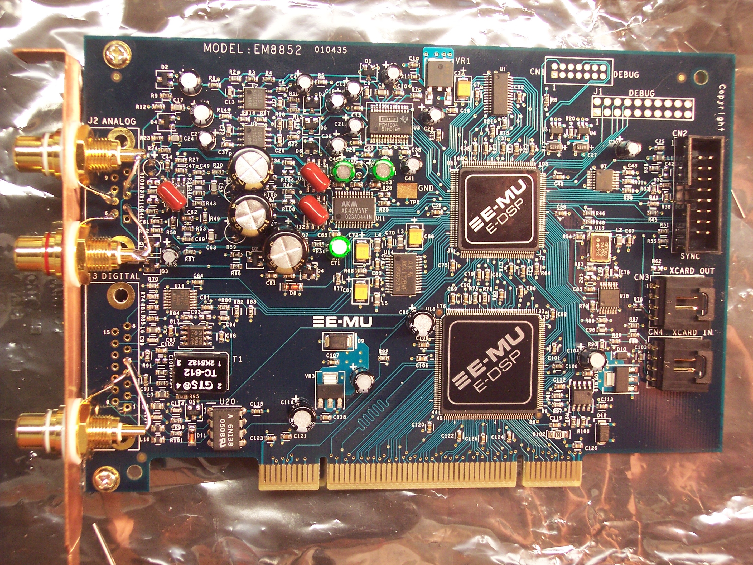 Due to the significantly larger size of the caps, some ended up on the backside of the card. Due to the significantly larger size of the caps, some ended up on the backside of the card. 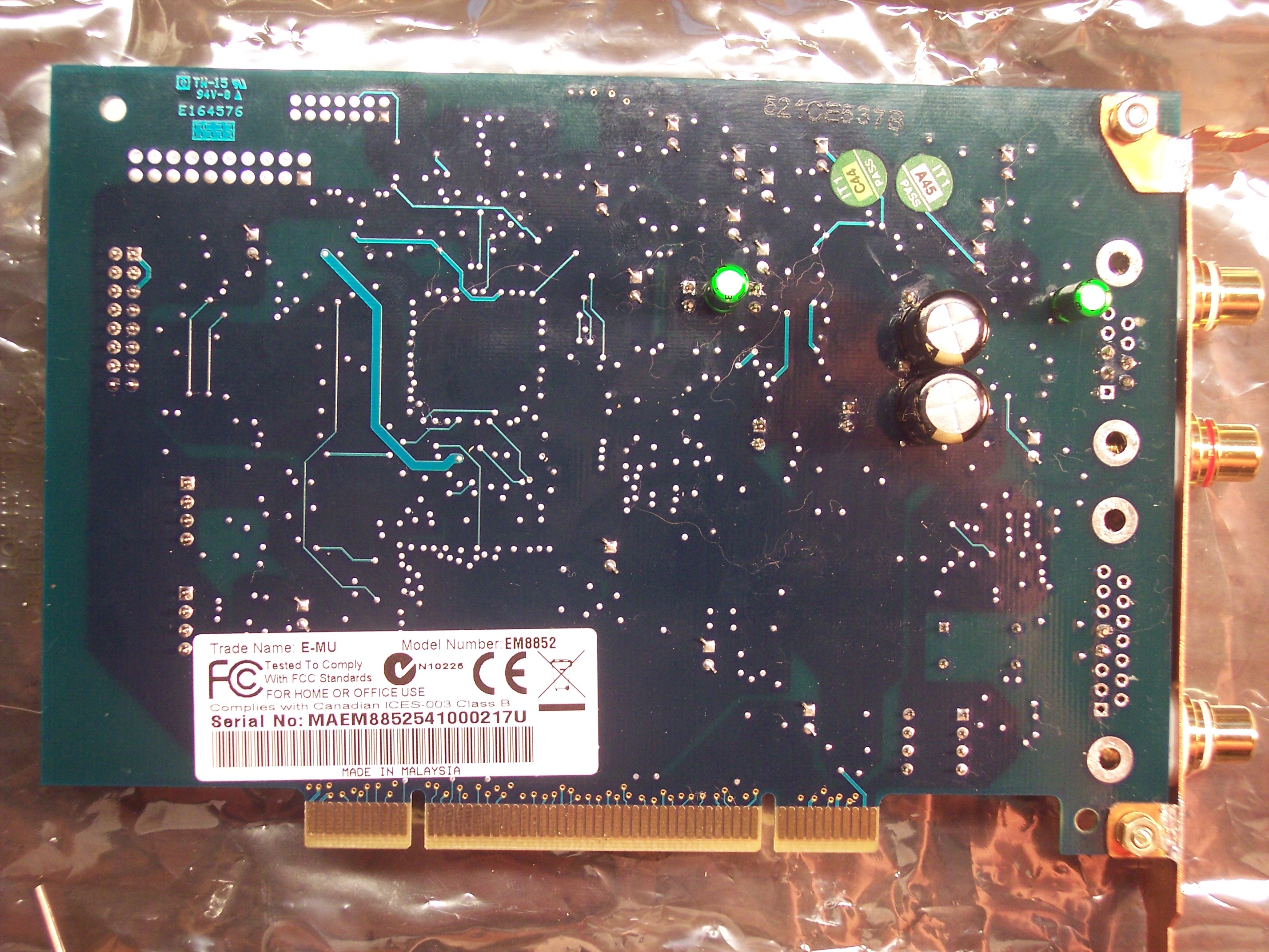 Now for testing... Tue Jun 6 10:20:32 CDT 2006 Finally got the card hooked up to the t-amp late last night. I can happily say that I didn't screw anything up -- it works. One small problem is that the output from the LT1364 op-amps is *very* high. I didn't put the scope on the output yet; that's a project for tonight. However, when the levels has been turned down in the emu mixer app, it sounds just fine. Looking at the specs sheet, the JRC component shows approximately a 40dB voltage gain in the audio frequencies, where the LT part is approximately 68dB. +28dB? Ahhh...the e-mu mixer shows their output slider values in dB -- it sounded "good" when adjusted to approximately -30dB. Maybe a coincidence? Maybe e-mu actually got the units right? Sun Jun 11 21:10:56 CDT 2006 Second card modified, just need to construct the case bracket. This version is using the Elna Cerafine caps. Modeling of the output circuit in OrCAD is underway. Goal of the modeling is to see if any other components in the output chain should be optimized somehow, and to appropriately change the components to reduce the overall gain of the LT1364. Now for testing... Tue Jun 6 10:20:32 CDT 2006 Finally got the card hooked up to the t-amp late last night. I can happily say that I didn't screw anything up -- it works. One small problem is that the output from the LT1364 op-amps is *very* high. I didn't put the scope on the output yet; that's a project for tonight. However, when the levels has been turned down in the emu mixer app, it sounds just fine. Looking at the specs sheet, the JRC component shows approximately a 40dB voltage gain in the audio frequencies, where the LT part is approximately 68dB. +28dB? Ahhh...the e-mu mixer shows their output slider values in dB -- it sounded "good" when adjusted to approximately -30dB. Maybe a coincidence? Maybe e-mu actually got the units right? Sun Jun 11 21:10:56 CDT 2006 Second card modified, just need to construct the case bracket. This version is using the Elna Cerafine caps. Modeling of the output circuit in OrCAD is underway. Goal of the modeling is to see if any other components in the output chain should be optimized somehow, and to appropriately change the components to reduce the overall gain of the LT1364. 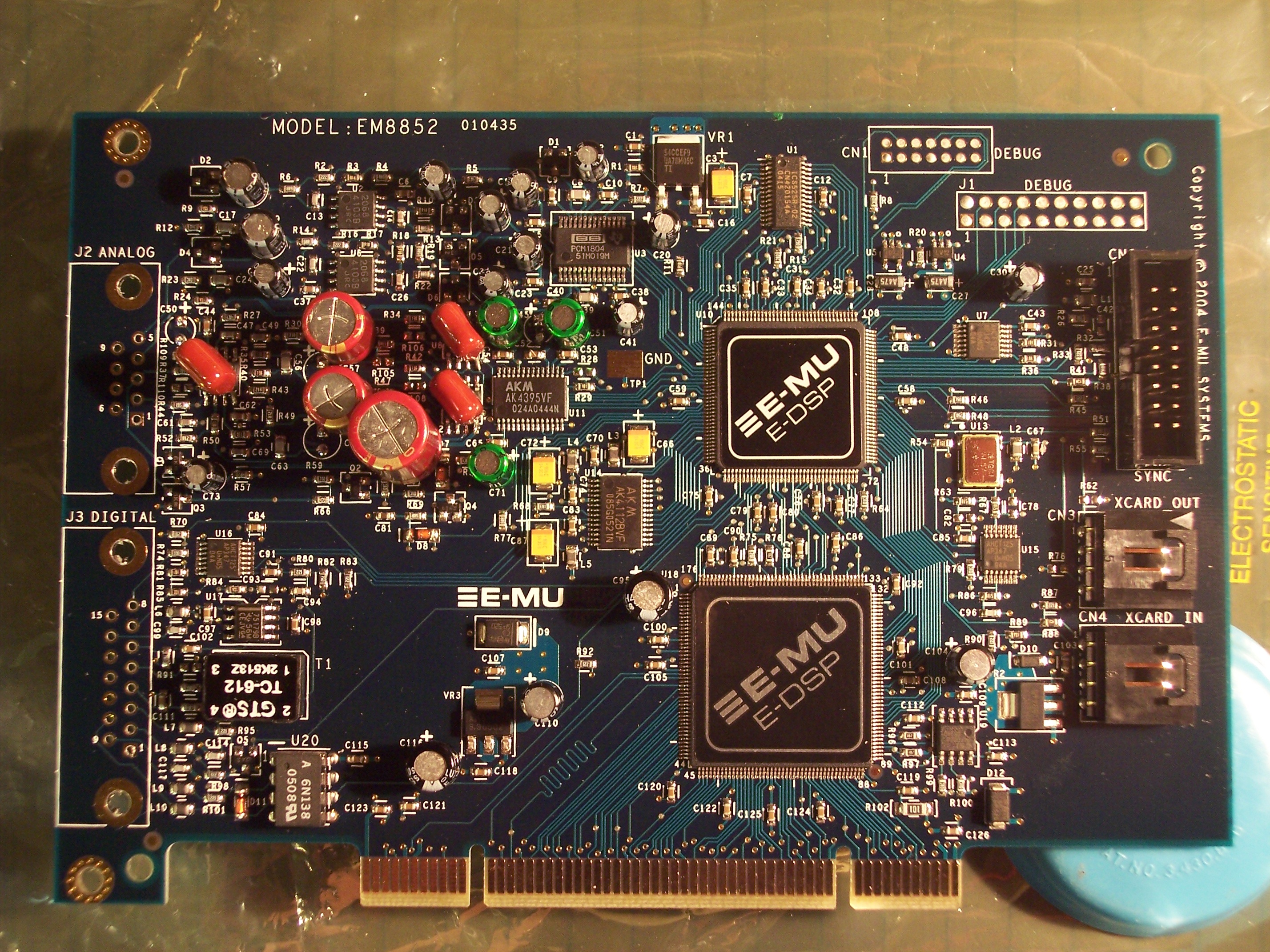 Mon Sep 25 16:03:01 CDT 2006 Third card modified -- this one has balanced XLR output. The input to the final LT1364 is balanced, so the balanced output is taken right from there. Not sure yet if this is the "right" place to get it, or what levels to expect here; more testing will be done. 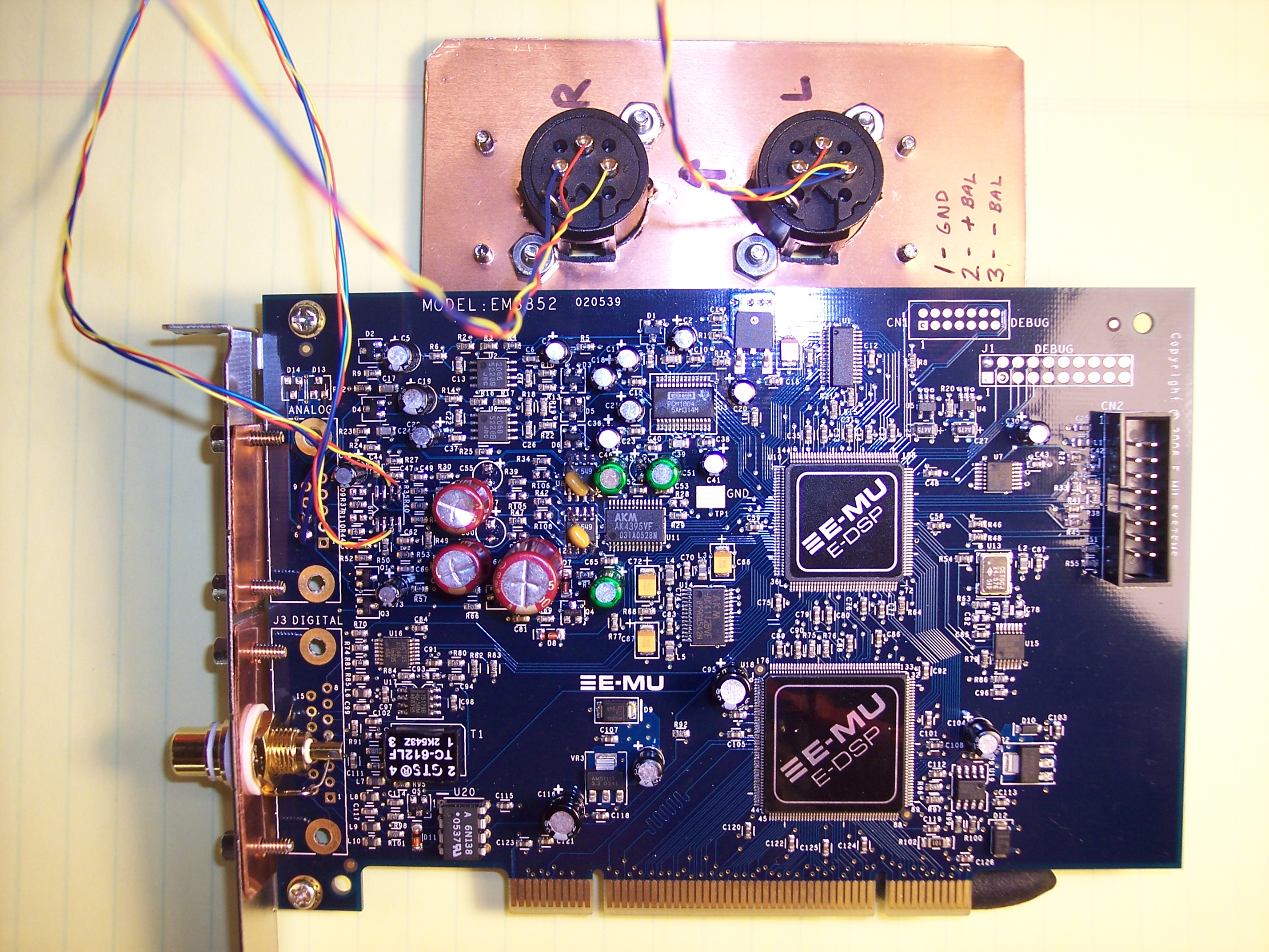 Sun Nov 19 21:18:04 CST 2006 Update: The card with the balanced output works well. Tested with a pair of powered monitors. This page last modified Sun Nov 19 21:20:35 CST 2006 by timc! |
| 欢迎光临 POPPUR爱换 (https://we.poppur.com/) | Powered by Discuz! X3.4 |